It’s shutdown week, and your electrical maintenance contractor just provided a spreadsheet with the results of their Megger testing on your facility’s critical motors. You’ve only loaded a few of the readings into your EAM when you get a notification from Motors@Work: “Polarization index of 1.93 indicates potentially bad windings on Compressor #2.”
Studies show that, depending on industry, motor windings cause 16% to 63% of motor failures[i], [ii] and that four out of five winding-related failures occur while the motor is in operation.[iii] But there are ways to assess your motor’s winding health — so you can act before it fails.
Here’s how Motors@Work helps our clients identify and troubleshoot motor winding issues that otherwise would have gone undetected without Motors@Work’s timely condition-monitoring alerts.
GAGING WINDING HEALTH
Whether form-, concentric-, lap-, or random-wound, all motors — ac and dc — use stator windings to create an electromagnetic field (and/or supplement the magnetic field created by permanent magnets). The copper — or sometimes aluminum — wire used in the windings comes coated in a thin mica- or glass-based epoxy that provides turn-to-turn insulation that keeps current flowing along the path of the conductor.
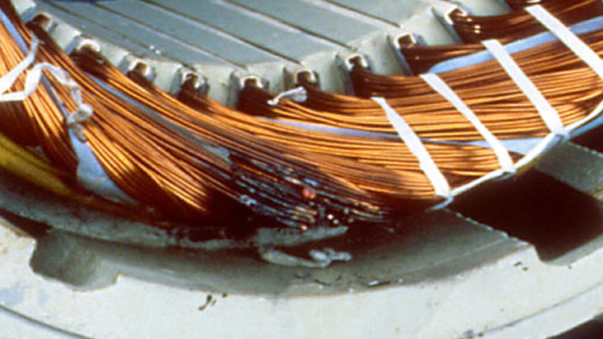
However, the process of inserting the windings into the slots or adding turns creates small scratches in the epoxy that reduce its thickness and therefore lessen its effectiveness — even straight from the manufacturer or rewind shop. Moreover, no insulation has perfect resistance. So, to ensure these scratches, voids, and other insulation imperfections do not affect motor operation, today most manufacturers and rewind shops vacuum-pressure impregnate the stator core (windings and laminations) with an extra dose of a resin epoxy that fills scratches and voids and cements everything in place. If you’ve ever opened up a motor to see a solid red or orange mass of a stator — where individual turns of wire and lacing are only visible in relief against the mass — that’s the impregnated resin.
Yet, these epoxies degrade over time — particularly when exposed to heat; corrosive moisture and chemicals, such as oil and dirt; over- and under-voltage operations; and inappropriate mechanical loads, such frequent starts and stops or overload operation.
Dating back to 1903,[iv] insulation resistance tests — often called Megger tests after the original and most-common brand-name testing device [like calling tissues Kleenexes and photocopies Xeroxes] — provide a nondestructive means of measuring epoxy resistance, and therefore, assessing winding health.
An insulation resistance testing device is a small, portable high-range (mega-Ohm [MW]) resistance meter with a built-in generator. The built-in generator typically produces a very-high, direct-current (dc) voltage and very small current, enabling a direct and instantaneous measurement of resistance per Ohm’s law. Dielectric testing devices are insulation resistance testers with the added feature of plotting current, voltage, and resistance over time throughout the 10-minute test.
To ensure accuracy, insulation resistance testing should only be conducted when the motor is cold — i.e., it’s been out of operation long enough that it has returned to room temperature, such as during a maintenance shutdown period. Additionally, the motor should be electrically disconnected, and the insulation testing device applied directly at the motor’s terminals to ensure your reading reflects the motor’s windings instead of the wires running from the MCC or drive to the motor. Once disconnected, discharge the motor’s capacitance by short-circuiting all leads to ground for at least 40 minutes prior to conducting the test. Also, since there’s value in trending the readings over time, use the same voltage setting each time you test a motor [refer to your testing device’s manual for proper voltage settings for your motor].
Because insulation resistance is a function of temperature and humidity, it’s difficult to compare insulation resistance measurements directly over time. Instead, we trend calculated values known as the polarization index and dielectric absorption ratio. These ratios normalize each reading, canceling out the effects of temperature and humidity.
The dielectric absorption ratio measures the amount of current needed to ionize the insulation as a percentage of the leakage current; it is calculated as the insulation resistance 30 seconds into the test divided by the insulation resistance at one minute. A value less than 1.25 or above 2.0 indicates your windings need attention.
 Since clean, dry, and healthy insulation’s resistance will continue to gradually increase for anywhere from 15 minutes to an hour into the test [Figure 1, above], the polarization index normalizes the insulation resistance at ten minutes by the resistance one minute into the test.[i] While higher or lower thresholds may be acceptable for certain specialty motors (e.g., higher-voltage [> 1kV] motors), a polarization index below 2.0 typically indicates very dirty windings and/or moisture penetration in the windings and a polarization index above 5.0 generally indicates brittle winding epoxy. Only proceed with a step-voltage or other over-voltage testing if the polarization index falls between 2.0 and 5.0 unless otherwise noted by the motor manufacturer. A negative trend in the polarization index over time indicates the buildup of dirt and contaminants, as shown in the figure below.

You open Motors@Work and view your polarization index and dielectric absorption ratios over time. You see that the value has been gradually decreasing over time, indicating the build-up of dust, oil, and moisture contaminants on the windings’ surface. You submit a work request to have the motor windings visually inspected; meanwhile, you check the availability of spares to ensure a quick replacement if the motor needs to be pulled for reconditioning.
Motors@Work’s continuous, near-real-time condition monitoring alerts catches potentially disruptive reliability performance trends that might have gone unnoticed otherwise. Additionally, our help content and content-rich alerts reduce the time required to troubleshoot the issue.
How will condition monitoring benefit your organization? Email Nicole at info@motorsatwork.com to learn more.
[i] Note: When the one-minute insulation resistance exceeds 5,000 MW, the polarization index may not be an effective indicator of insulation condition. At that point, current draw falls to the microampere level (mA), outside the accurate range of most test devices.
[i] O.V. Thorsen & M. Dalva, “A survey of faults on induction motors in the offshore oil industry, petrochemical industry, gas terminals, and oil refineries,” Proceedings of the IEEE Petroleum & Chemical Industry Conference (1994), Paper # PCIC-94-01.
[ii] Allianz Insurance (Germany), “Monitoring und diagnose elentrischer Maschinen und Antriebe,” VDE Colloquium, 28 June 2001.
[iii] One-third of motor winding failures occur in operation, versus 8% of winding failures found during offline inspections. Source: GK Singh and SAS Al Kazzaz, “Induction machine drive condition monitoring and diagnostic research — a survey.” Electric Power Systems Research 64.2 (2003).
[iv] Megger, “A Stitch in Time: The complete guide to electrical insulation testing,” 2006.
[v] Note: When the one-minute insulation resistance exceeds 5,000 MW, the polarization index may not be an effective indicator of insulation condition. At that point, current draw falls to the microampere level (mA), outside the accurate range of most test devices.